
Sustainable Energy Control and Optimization
ISSN: request pending (Online) | ISSN: request pending (Print)
Email: [email protected]

Electricity has become an essential part of modern life, influencing nearly every aspect of daily activities and technological advancements. In today's industrial era, electronic technology plays a crucial role in industries ranging from small-scale businesses to large manufacturing operations. One of the most fundamental electronic components found in everyday applications is the rectifier circuit. A rectifier is an electrical circuit designed to convert an alternating current (AC) voltage into a direct current (DC) voltage, making it indispensable in various electronic devices such as phone chargers and power adapters [1, 2].
The rectifier's primary function is to convert AC into DC, ensuring that electronic devices receive a stable and usable power source [3]. A key component in rectifier circuits is the diode, a semiconductor device that allows current to flow in only one direction. Despite its widespread use, the characteristics and performance of rectifier circuits are not always fully understood, making research and experimentation essential to optimizing their efficiency.
Beyond rectifier circuits, synchronous generators commonly referred to as alternators also play a crucial role in power generation. These machines operate based on the principles of electromagnetic induction, converting mechanical energy into electrical energy [4]. Alternators are widely used as power generation sources, both on small and large scales, and are integral to renewable energy applications. In Indonesia, for example, electrical power is generated using hydroelectric power plants (PLTA), which harness the movement of river water to drive turbines, as well as wind power plants (PLTB), which utilize wind speed to generate mechanical energy that is then converted into AC electricity through generators. This energy is then distributed through power grids to homes and businesses.
The use of a single-phase AC generator or alternator in an uncontrolled half-wave rectifier circuit with a reciprocating load presents certain challenges. One of the main issues is that the output voltage requires further filtering to make it suitable for electronic devices that require a stable DC power source [5]. In such rectifier circuits, both diodes and capacitors play crucial roles. While diodes are responsible for rectification, capacitors act as filtering components, reducing ripple voltage to create a smoother DC output [6, 7].
Therefore, an in-depth study is necessary to understand how each component in the rectifier circuit functions and how their interactions impact performance. Through analysis and experimental testing, valuable data can be gathered to enhance rectifier circuits, ensuring optimal power conversion for various electronic applications.
These findings offer valuable insights into the role of capacitors in enhancing the quality of power output from single-phase AC generators. Although the basic principles are well-established, their relevance remains strong, particularly in modern applications requiring efficient and decentralized power solutions such as renewable energy systems and portable electronic devices.
This section reviews previous studies relevant to this research, offering an overview of existing findings and advancements in the field. These studies provide a foundation for understanding the current research landscape, identifying knowledge gaps, and positioning this study within the broader context. By analyzing related literature, this research builds upon established knowledge and aims to contribute new insights to the subject.
Georgakas et al. [1] proposed a comprehensive design methodology for rectifier circuits in RF energy-harvesting systems targeting ultra-low-power applications. Their evaluation covers multiple topologies—including Schottky diode-based rectifiers, CMOS charge-pump configurations, and impedance-matching networks—to maximize power transfer from ambient RF sources. The study also explores the use of advanced semiconductor materials (e.g., GaAs) and cutting-edge CMOS processes to enhance rectifier performance at extremely low input power levels (below –20 dBm). Through analytical modeling and experimental validation, they demonstrate that power conversion efficiency (PCE) is highly sensitive to input impedance, operating frequency, and nonlinear device losses. Additionally, employing dynamic impedance-adaptation techniques and judicious material selection is shown to substantially improve PCE under ultra-low-power conditions.
The implications of this study are highly relevant in the development of battery-free electronic systems, which have the potential to reduce dependence on conventional power sources and accelerate the adoption of sustainable technologies in a variety of applications, including wearable devices, environmental sensors, and renewable energy-based wireless communication systems [1, 8].
Karafil et al. [2] introduce and analyze a 15-level inverter topology that minimizes the number of switches while maintaining high output power quality. A key aspect of their design is the strategic use of capacitors to optimize voltage levels and enhance overall efficiency.
In the proposed topology, capacitors play a crucial role in voltage balancing and energy storage, helping to maintain a stable DC-link voltage while reducing the reliance on additional active components. By carefully selecting the capacitance values and placement, the inverter can achieve a more uniform voltage distribution across the switching network, which contributes to lower voltage stress on semiconductor devices and improved overall reliability.
Moreover, the capacitors assist in reducing total harmonic distortion (THD) by smoothing voltage transitions between levels. This effect is particularly beneficial in high-power applications, where excessive harmonics can lead to energy losses and electromagnetic interference (EMI). The study also explores different capacitor configurations, including series and parallel arrangements, to determine the optimal setup for minimizing switching losses and improving inverter performance [2, 8].
Experimental validation and simulations confirm that incorporating capacitors efficiently in the inverter design leads to enhanced energy conversion and better output waveform quality. The results suggest that this capacitor-based approach not only improves power electronics performance but also supports the advancement of renewable energy systems and industrial motor drives by providing a more cost-effective and efficient multilevel inverter solution [1, 8].
Drapela et al. [3] develop a SCADA-based low-cost single-phase AC generator control laboratory kit designed for educational and experimental purposes. The study aims to enhance practical learning experiences by integrating real-time monitoring and control capabilities into generator systems, allowing users to explore various aspects of power generation, voltage regulation, and automation.
A key feature of the laboratory kit is its ability to simulate real-world conditions in single-phase AC generators, enabling users to analyze generator behavior under different load conditions and voltage fluctuations. The SCADA integration facilitates remote monitoring and control, allowing students and researchers to observe real-time data on voltage, current, frequency, and power output. This capability provides deeper insights into generator performance, efficiency optimization, and fault detection, which are crucial for modern power engineering applications.
The study also explores the role of excitation control and capacitor compensation in single-phase AC generator operation. By implementing capacitors in the system, the laboratory kit demonstrates techniques for reactive power compensation, improving voltage stability and power factor correction. This is particularly important in standalone power systems where voltage regulation is a challenge. The researchers analyze how different capacitor configurations affect the generator's voltage profile, transient response, and overall efficiency [3, 8].
Experimental validation confirms that the laboratory kit enhances accessibility to hands-on training, making it a valuable tool for both academic and industrial applications. The findings suggest that this approach not only improves the understanding of single-phase AC generators but also fosters innovation in the development of more efficient and intelligent generator control systems. Additionally, the low-cost and modular design of the kit makes it an ideal solution for institutions with limited resources, supporting the advancement of sustainable and smart energy technologies.
In this section, the materials and software used in the research will be described.
A synchronous generator is a device that transforms mechanical energy into electrical energy. It functions on the principle of electromagnetic induction, as outlined by Faraday's Law of Induction, which states: "When the magnetic flux through a coil changes, it induces an electromotive force (emf) within the coil. The magnitude of the induced emf is directly proportional to the rate at which the magnetic flux changes [9, 10].
The generator includes a rotor with a field winding powered by direct current. This current generates a rotating magnetic field that synchronizes with the rotor's speed and direction [11]. As the rotor's magnetic field rotates, it induces a changing magnetic flux in the stator coils, which results in the generation of an electromotive force (emf) at the terminals of the coils [12, 13]. The following is a picture of a synchronous generator in Figure 1.

A synchronous generator consists of two key components: the field coil on the rotor and the armature coil on the stator. The field coil can be constructed in various forms, such as shoe poles or cylindrical types, while the armature coil is designed similarly to those found in induction machines.
The operation of the generator follows these steps:
The excitation source connected to the rotor provides direct current to the field coil, generating a constant magnetic field [14].
The prime mover, attached to the rotor, rotates at a steady speed, creating a rotating magnetic field that is transferred to the stator.
This rotating magnetic field induces a time-varying magnetic flux in the stator coils, leading to the generation of voltage (emf) according to Faraday's Law.
In single-phase synchronous generators, the electromotive force (emf) plays a crucial role in inducing current in the armature coil. When a metal is exposed to an electric field, the free electrons within it move, creating an opposing electric field that generates the emf. This emf continuously drives the movement of electrons, ensuring the flow of current.
The emf source, often a battery or another voltage source, maintains a potential difference across the coil, ensuring that current flows continuously and the induction process remains active.
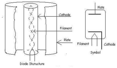
A diode, as shown in Figure 2, is a two-electrode electronic component that permits current to flow exclusively in one direction, which makes it crucial for the operation of rectifier circuits. The fundamental role of a diode is to convert alternating current (AC) into direct current (DC) by allowing current to pass during one half of the AC cycle while blocking it during the other half [15]. This functionality is the foundation of rectification processes in power electronics, where converting AC into DC is required for powering various devices and systems. The invention of the diode dates back to 1904 by J.A. Fleming, who developed the first practical vacuum tube diode. Since then, diodes have evolved significantly, transitioning from vacuum tubes to semiconductor diodes, which are more efficient, reliable, and compact. Today, diodes are ubiquitous in electronic circuits, playing a vital role not only in rectification but also in signal modulation, protection circuits, and voltage regulation. Their versatility and essential functionality make diodes a cornerstone component in modern electronic and electrical engineering applications [16, 17].
The methodology for this research was conducted at the Power Electronics Laboratory, utilizing a range of equipment and tools. The hardware setup included a laptop with an AMD Ryzen 3 3200U processor (2.6 GHz), Radeon Vega Mobile Gfx, 8 GB RAM, 512 GB SSD, and a 14" Full HD IPS LCD LED screen (1920 x 1080 pixels), running on the Windows Home x64 operating system. Electronic components used for the experiment included single-phase semi-controlled wave rectifier modules, single-phase AC generators (alternators), AC/DC voltmeters, AC/DC ammeters, transformers, resistors, diodes, electrolyte capacitors (Elco), oscilloscopes, and connecting cables. For simulation purposes, the Power Simulator (PSIM) software was selected due to its capability to streamline the analysis of output waveforms and network characteristics.
The research process involved several steps: preparation of the required tools and materials, circuit design based on the schematic, setting parameter values for each component, and taking measurements such as RMS input voltage, RMS input current, DC output voltage, DC output current, RMS output voltage, and RMS output current. Input and output voltage waveforms were observed using an oscilloscope, and the results were compared with theoretical values to calculate the percentage difference [18]. Additionally, an analysis of the characteristic parameters of the circuit was performed to draw conclusions [19].
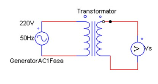
This study employed a half-wave rectifier circuit with a capacitor filter, using a single-phase AC generator as the voltage source. A transformer was used to step down the input voltage before it entered the rectifier, which converted the AC voltage into a half-wave DC output [20]. The system block diagram outlined the assembly stages, which included the AC generator with a transformer, a half-wave rectifier with a resistive load, the addition of capacitors as filters, and the measurement of results using voltmeters, ammeters, and oscilloscopes to assess system performance. This methodology is significant for publication in journals or engineering proceedings as it provides a comprehensive analysis of power electronic systems in energy conversion, underpinned by both empirical data and simulation validation.
At this stage, the voltage drop system from a single-phase AC generator source, initially set at 220 V, is designed to be reduced using a transformer. The goal is to produce an output voltage of 30 VAC. To calculate the number of secondary turns (Ns), the transformer formula is applied as follows:
By entering the primary winding value () and the desired secondary voltage, the calculated value for the secondary turns () was obtained. This calculation corresponds to the transformer configuration used for voltage reduction. Based on this setup, the simulation results show that the output voltage of the transformer is 30 VAC, as depicted in Figure 3. Furthermore, the actual measurements align closely with the theoretical calculations, indicating that the transformer design is accurate and effective in lowering the voltage as intended. The consistency between the simulation and real-world measurements supports the reliability of the transformer's performance in this application.
| Shell (rms) | Is (rms) | Vo (DC) prac | Vo (DC) theory | Io (DC) prac | Vo (rms) theory | Vo (rms) prac | Io (rms) prac |
|---|---|---|---|---|---|---|---|
| 30 | 0.085 | 13.15 | 13.51 | 0.054 | 21.21 | 20.76 | 0.085 |
| 45 | 0.133 | 21.21 | 20.26 | 0.087 | 31.36 | 32.57 | 0.133 |
| 60 | 0.17 | 26.65 | 27.01 | 0.109 | 42.42 | 41.97 | 0.17 |
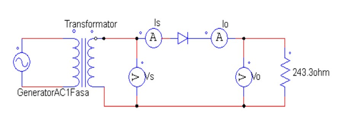
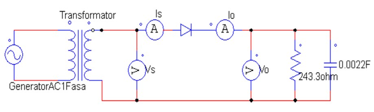
The uncontrolled half-wave rectifier circuit is designed using essential components that facilitate the conversion of alternating current (AC) to direct current (DC). These components include a diode, which serves as the primary rectifying element, allowing current to flow in only one direction while blocking the reverse flow. Additionally, a resistor with a load value of 243.3 Ohms is incorporated to regulate the current and voltage levels within the circuit. To further enhance the output characteristics, an electrolytic capacitor with a capacitance of 2200F is employed as a filtering component, helping to smooth the rectified voltage by minimizing fluctuations and reducing ripple.
This rectifier circuit is integrated with the pre-designed transformer system, which steps down the AC voltage to a suitable level before rectification. To accurately assess the circuit's performance, voltmeters and ammeters are strategically placed to measure both input and output voltage and current, ensuring precise monitoring of electrical parameters. Figure 4 illustrates the circuit configuration without the filter, showcasing the raw rectified output, which typically exhibits significant ripple. In contrast, Figure 5 depicts the same circuit with the filter integrated, highlighting the improvement in voltage stability. The addition of the filtering capacitor plays a crucial role in refining the DC output, reducing voltage variations, and providing a more consistent and reliable power supply for the connected load. This enhancement is particularly important in applications where steady voltage levels are required to ensure the proper functioning of electronic components and systems.
| Shell (rms) | Vo (DC) prac | Vo (DC) theory | Error % | Vo (rms) theory | Vo (rms) prac | Error % |
|---|---|---|---|---|---|---|
| 30 | 13.15 | 13.51 | 2.66 | 21.21 | 20.76 | 2.12 |
| 45 | 21.21 | 20.26 | 4.68 | 31.36 | 32.57 | 3.85 |
| 60 | 26.65 | 27.01 | 1.33 | 42.42 | 41.97 | 1.06 |
The simulation results show that at an input voltage of 30 VAC (Vrms), the peak voltage (Vm) will be 42.43 V.
The unfiltered output wave is visualized in Figure 6, which shows the typical half-wave pattern. This waveform exhibits an unstable amplitude, with significant ripple, indicating the presence of alternating fluctuations between peaks. This instability in the output is characteristic of a half-wave rectifier without any filtering mechanism in place. The unfiltered signal can cause inefficiencies and potential damage to sensitive electronic components, highlighting the need for a filtering stage in the rectifier circuit.

Simulation results are summarized in Table 1, which compares measured and calculated values for key parameters—such as input and output voltage, current, and other system characteristics—under various conditions, thereby providing a basis for evaluating how well the simulated circuit matches theoretical expectations.
In Table 2, the percentage of error between the simulation results and the theoretical calculations is presented.
| Shell (rms) | Is (rms) | Vo (DC) prac | Vo (DC) theory | Io (DC) prac | Vo (rms) theory | Vo (rms) prac | Io (rms) prac |
|---|---|---|---|---|---|---|---|
| 30 | 5.85 | 40.66 | 41.63 | 1.06 | 41.63 | 40.9 | 5.85 |
| 45 | 8.87 | 61.68 | 62.45 | 1.62 | 62.45 | 62.05 | 8.87 |
| 60 | 12 | 82.67 | 83.26 | 2.17 | 83.26 | 83.17 | 12 |
| Shell (rms) | Vo (DC) prac | Vo (DC) theory | Error % | Vo (rms) theory | Vo (rms) prac | Error % |
|---|---|---|---|---|---|---|
| 30 | 40.66 | 41.63 | 2.33 | 41.63 | 40.9 | 1.11 |
| 45 | 61.68 | 62.45 | 1.23 | 62.45 | 62.05 | 0.64 |
| 60 | 82.67 | 83.26 | 0.708 | 83.26 | 83.17 | 0.108 |
When a filter capacitor is added to the rectifier circuit, the output voltage (Vdc) becomes significantly more stable, enhancing the overall performance of the system. The capacitor functions by storing electrical energy during the peaks of the rectified voltage and discharging it during the valleys, effectively smoothing out fluctuations. As a result, the output waveform transitions from a pulsating DC signal to one that more closely resembles pure direct current (DC). This process significantly reduces ripple voltage, which is a measure of the unwanted variations in the output. The decrease in ripple indicates that the filter capacitor is effectively stabilizing the voltage, improving the quality of the DC supply.
A smoother and more stable DC voltage is particularly crucial for powering sensitive electronic components that require precise and consistent voltage levels to function optimally. Devices such as DC motors, microcontrollers, and other semiconductor-based systems rely on a steady power supply to ensure accurate performance and prevent potential malfunctions. In applications where voltage fluctuations could lead to inefficiencies, erratic behavior, or even long-term damage to components, the inclusion of a filter capacitor becomes essential. By improving voltage stability, the capacitor not only enhances system reliability but also extends the lifespan of connected electronic devices, making it a fundamental component in rectifier circuits used for power conversion and regulation. Figure 7 showing the simulation results of the input and output wave rectifier after filtering.
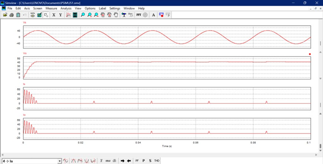
The measurement and simulation results are summarized in Table 3, while the percentage error between the simulation results and the theoretical calculations is shown in Table 4.
This experiment concluded that increasing the value of the filter capacitor leads to a reduction in ripple voltage, resulting in an output that closely approximates pure DC voltage. In the case of the uncontrolled half-wave rectifier circuit, the output voltage at the resistive load is found to be approximately equal to the peak voltage of the transformer output, minus a voltage drop of 0.7 V due to the forward bias of the silicon diode. The findings suggest that the integration of the transformer and rectifier circuit effectively optimizes the conversion of AC to DC, with the simulation results showing minimal discrepancy compared to the theoretical calculations. This confirms the efficiency and accuracy of the system in achieving reliable DC output.
Although rectifier circuits and their components have been widely studied, this research reinforces their continued relevance in modern contexts. The role of capacitors in improving output quality highlights their importance in small-scale power systems, especially in applications that demand stable such as renewable energy installations and portable electronic equipment.
 Copyright © 2025 by the Author(s). Published by Institute of Emerging and Computer Engineers. This article is an open access article distributed under the terms and conditions of the Creative Commons Attribution (CC BY) license (https://creativecommons.org/licenses/by/4.0/), which permits use, sharing, adaptation, distribution and reproduction in any medium or format, as long as you give appropriate credit to the original author(s) and the source, provide a link to the Creative Commons licence, and indicate if changes were made.
 Sustainable Energy Control and Optimization
ISSN: request pending (Online) | ISSN: request pending (Print)
Email: [email protected]

Portico
All published articles are preserved here permanently:
https://www.portico.org/publishers/iece/