


Sustainable Energy Control and Optimization
ISSN: request pending (Online) | ISSN: request pending (Print)
Email: [email protected]

The study of aerodynamics is a vital part of engineering design with many applications in many fields. As various industries have become increasingly concerned about energy efficiency, improvements have been made to the design of machines and structures to minimize their energy consumption. Wind turbines, vehicles, and buildings can all be enhanced using aerodynamic principles. For example, lowering a vehicle's coefficient of drag () can improve fuel efficiency. Researchers have conducted extensive research regarding the benefits of various drag-reducing tools, including spoilers, wings, front splitters, and Vortex Generators (VGs). The use of VGs has been demonstrated to decrease vehicle drag while also providing additional benefits, such as reducing rear window scuffing. Due to their subtle appearance, VGs are easier to install and remove than other drag reduction tools. In addition, they cause no lasting damage to the mounting surfaces, which could affect the vehicle's resale value. Consequently, VGs have become an increasingly popular choice among engineers and designers in the transportation sector [1]. Bernoulli's principle is a fundamental concept in aerodynamics, a key principle in the aviation industry. The Bernoulli principle states that as fluid speed increases, pressure decreases. Air that flows over a curved surface must expand faster than air that flows over a flat surface. This results in a difference in pressure between the top and bottom surfaces of an airplane's wing, for example. When the pressure differs, lift is generated, allowing airplanes to remain in flight [2].
There are four fundamental concepts that govern objects movement through the air. This includes drag, which is the resistance air presents to a moving object and has an adverse effect on vehicle speed and fuel efficiency. Alternatively, lift refers to the force air exerts on a wing or body. This results in reduced drag and increased lift, such as car spoilers and airplane wings. High-performance vehicles, such as racing cars and sports bikes, require downforce to improve grip and stability. Air exerts downward force on the wings and bodies to create downforce. Finally, turbulence is characterized by chaotic and unpredictable airflows that surround objects, which can adversely affect vehicle stability, lift, and drag [3, 4].
Many owners today modify their daily drivers to make them appear sportier. With increased horsepower under the hood, the aerodynamic properties may become inadequate to provide the required downforce and handling. Performance, handling, safety, and comfort are heavily influenced by aerodynamic characteristics. A variety of aerodynamic aids are added to the bodywork, such as rear spoilers, lower front and rear bumpers, air dams, and many others to enhance vehicle efficiency and reduce drag while increasing stability [5].
VGs are one of the devices used in aerodynamics. They create swirls or disturbances in the air to process airflow around a surface. These VGs such as wings, fins, or vehicle surfaces are typically small, angle-mounted structures designed to enhance vehicle aerodynamic performance. As early as the 1970s, engineers began experimenting with devices to improve racing cars' performance using VGs.
Vehicle aerodynamic performance can be greatly enhanced by VGs. VGs have been demonstrated in several studies to reduce drag by delaying air flow separation, which can result in increased fuel efficiency and higher speeds. In other words, VGs reduce drag by energizing the boundary layer of air flowing over a surface. By doing so, flow separation is prevented, which is a major cause of drag. By maintaining smooth airflow, VGs improve aerodynamic efficiency and minimize drag forces [6, 7]. Additionally, VGs can enhance vehicle handling and performance by increasing lift. Furthermore, VGs can enhance the vehicle's stability by directing airflow in a specific direction, reducing accident risk. A variety of factors determine VGs' effectiveness, including their application, design, the vehicle's shape and speed, and other factors. If the VGs are not properly positioned or designed, they may reduce stability or increase drag. It is imperative that the VGs are sized and positioned correctly to achieve the desired aerodynamic effects [8, 9].
The use of actively controlled spoilers may increase the lateral stability and safety of high-speed vehicles by producing the necessary downforce while maintaining an acceptable level of induced drag. In racing cars, fixed spoilers are used to increase downforce and enhance lateral stability. Fixed spoilers can produce up to two times the vehicle's weight in terms of downforce [10].
A spoiler is an aerodynamic device commonly used in cars to improve performance, stability, and fuel efficiency. These devices reduce drag and increase downforce by altering the airflow around the vehicle. In addition to improving the aerodynamic performance of a car, spoilers serve other purposes as well. During high-speed driving, air flows over the car and creates a low-pressure area behind it. In this low-pressure area, drag is created, which can reduce the vehicle's fuel efficiency and cause it to slow down. A spoiler reduces the size of the low-pressure area behind a car by disrupting the flow of air over it. By reducing drag, the car can be driven faster and handled better. A spoiler can reduce a car's drag coefficient by up to 15% [11]. Another purpose of spoilers is to improve the traction of a vehicle, particularly when the vehicle is turning at high speeds. Cars can lift or lose traction when turning at high speeds due to air flowing over them. By creating downforce, a spoiler keeps the car firmly planted on the road.
Vehicle downforce is the force that pushes its tires down the road to increase traction. As a result of a spoiler, air is deflected downward, increasing the weight exerted on the tires, which creates downforce. The use of spoilers can increase the downforce of a car by as much as 60% [12].
In computational fluid dynamics (CFD), numerical analysis and algorithms are used to analyze and solve problems related to fluid flow. Modeling and simulating fluid behavior in different scenarios is achieved by employing a variety of functions in this field. The purpose of this study is to examine the impact of the spoiler and VG on the aerodynamics of the Audi R8 using ANSYS Fluent 19.2. Furthermore, the VG will be examined in terms of how it affects the shape of the vehicle. Additionally, a comparison will be made between the condition of the vortex generator and its absence from the vehicle. To select the best spoiler shape, multiple cases of spoiler shapes will be studied to determine which gives the best results.
Modern vehicles have become more visually appealing with the addition of spoilers, which improve the performance of these vehicles as well as add aesthetic appeal. In order to improve a vehicle's aerodynamics, spoilers are wing-like structures attached to its rear. As a result, it reduces drag and improves downforce, increasing vehicle stability and handling at high speeds. Market spoilers come in a variety of styles and designs, each with its own purpose and design. A description of the various types of spoilers found on vehicles will be presented in this section. In addition, there will be descriptions of their functions and definitions.
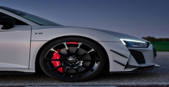
Front Spoiler: also known as a "chin spoiler". This spoiler reduces lift and improves stability at high speeds by being mounted on the front of the car. It has been shown that front spoilers can reduce the lift coefficient of a car by 23-25% [13]. There are a number of lightweight materials that can be used for front spoilers, including plastic and fiberglass. There are several types of aerodynamic shapes available, from simple curved shapes to more aggressive designs with integrated fins and other aerodynamic features. An example of a front spoiler is shown in Figure 1.
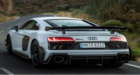
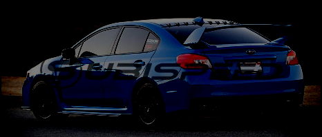
Wing Spoiler: also known as "rear spoiler". A spoiler of this type is a large, prominent device attached to the rear of a vehicle. In addition to improving traction and stability, it provides additional downforce at high speeds. A wing spoiler can increase car downforce by up to 1000 Newtons [15]. There are many different types of wing spoilers, ranging from a simple flat plane to a complex multi-element design with integrated fins. An example of a wing spoiler is shown in Figure 2.
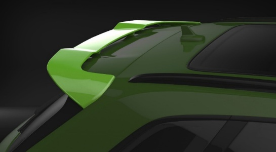
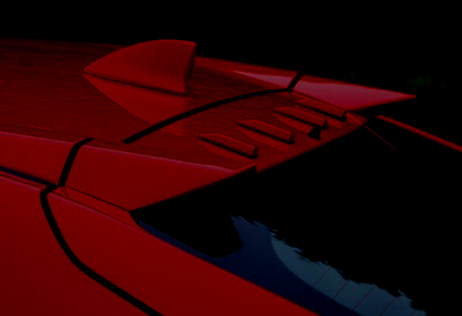
Roof Spoiler: The rear edge of the roof is equipped with this type of spoiler, which reduces drag and improves airflow for improved aerodynamics. In some cases, roof spoilers can reduce a car's drag coefficient by 5% [17]. It is possible to find roof spoilers in a variety of shapes, ranging from a simple flat configuration to an angled configuration with integrated fins and other aerodynamic features. An example of a roof spoiler is shown in Figure 3.
Mid Spoilers: also known as mid-wing spoilers or center spoilers. The spoilers are mounted in the middle of the rear of the car, between the taillights. The purpose of these devices is to increase the car's stability and handling at high speeds by increasing downforce. They are generally found on high-performance sports cars and racing cars. It is estimated that mid spoilers can increase a vehicle's downforce by as much as 15%. Results showed that the mid spoiler increased the rear downforce of the car, improving its handling and stability [19]. In addition to improving cornering ability, the mid spoilers can also reduce oversteer and improve the balance between the front and rear of the car [20].
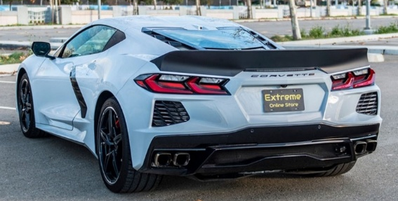
Ducktail Spoilers: also known as "whale tail". These are rear spoilers that extend upwards and downwards from the rear edge of the trunk or hatch of a vehicle, resembling the tail of a duck or whale. Typically, these devices are found in high-performance sports cars and racing cars and are designed to enhance a car's stability and handling during high-speed maneuvers. A ducktail spoiler can increase a car's downforce by up to 9% [21]. It should be noted, however, that adding a ducktail spoiler to a vehicle may also increase drag and reduce fuel efficiency. To ensure that a spoiler is installed correctly and does not negatively affect the performance of the vehicle, it is recommended that you choose one that is specifically designed for the vehicle. An example of a ducktail spoiler is shown in Figure 4.
Depending on their intended purpose and the specific needs of the vehicle, spoilers are available in a wide range of shapes and configurations. Various types of spoilers are available, some of which have a flat and smooth surface, while others may have a curved or angled surface to aid in the redirection of airflow. Furthermore, some spoilers may incorporate fins or other features to assist in controlling the flow of air over the vehicle. Finally, there are a number of factors that influence the shape of a spoiler, including the vehicle's size, weight, speed, and intended use.
Airflow around a vehicle is controlled and modified by VGs, which are small aerodynamic devices. The automotive industry uses them extensively to improve the performance and efficiency of cars, trucks, and other vehicles. The purpose of VGs is to create small vortices in the airflow, which reduce drag and turbulence while improving handling and stability. It is important to note that there are various types of VGs available on the market, each of which has its own purpose and design.
Roof-mounted VGs: Generally, they are used to improve the aerodynamic performance of vehicles, particularly trucks and buses. Their purpose is to produce vortices that energize the boundary layer and reduce turbulence, thus reducing drag and improving fuel efficiency. By using VGs, the drag coefficient of the truck was reduced by 3.3% and fuel efficiency was improved by 2.9% [23]. As a result of the improved vortex generators, the drag coefficient of the bus was reduced by 5.5% and the fuel efficiency was improved by 2.2% [24]. An example of a VGs mounted on the roof is shown in Figure 5.
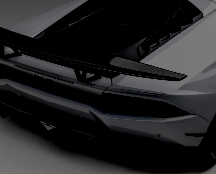
Delta Wing VGs: This type of VG has triangular fins that generate large vortices that reduce drag and increase downforce. It is common to find them in race cars and high-performance sports cars. As a result of delta wing vortex generators, lift is increased and drag is reduced by up to 10% [26]. Material options for delta wing vortex generators (VGs) include metal, plastic, and composites. As illustrated in Figure 6, an example of these VGs is mounted on the rear of a Lamborghini Huracan.
W-shaped VGs: These VGs are small. An aerodynamic surface of an aircraft consists of protrusions in the shape of a W. Those protrusions generate vortices that enhance airflow over the surface and delay separation of the flow, thus reducing drag and increasing lift. In comparison with the traditional VGs, the W-shaped VG produces a stronger and more effective vortex. Vehicles can also benefit from W-shaped VGs in terms of aerodynamic performance. Using VGs, energized boundary layers are created that improve airflow around the vehicle, reducing drag and increasing fuel efficiency. By using W-shaped VGs, the aerodynamic performance of the car was improved by 5%, and the lift coefficient was increased by 3% [28]. In another study, W-shaped VGs were utilized on a commercial truck. Numerical simulations were used to optimize the placement and size of the VGs on the truck. The optimized configuration was then tested in a wind tunnel. Results showed that the W-shaped VGs reduced the drag coefficient of the truck by 7.5% and improved its fuel efficiency by 2.2% [29]. An example of a W-shaped VG is shown in Figure 7.
Serrated VGs: They are small VGs with triangular-shaped protrusions placed on aircraft's wings or other aerodynamic surfaces. By creating vortices over the surface, they enhance airflow and reduce drag, thereby increasing lift. By generating more turbulence via the serrated shape of the VG, a stronger vortex is created. This contributes to a significant reduction in lift and drag. A higher lift-to-drag ratio was achieved by the serrated VGs because they increased lift coefficients and reduced drag coefficients [31]. An example of a serrated VG is shown in Figure 8.

In aerodynamics, the Bernoulli principle describes the relationship between air velocity and pressure. In order to design more efficient and effective vehicles, it is essential to understand how aerodynamics and the Bernoulli principle interact. According to Bernoulli's principle, the pressure exerted by fluids (such as air) decreases as their velocity increases [33, 34, 35]. To understand how air flows around objects, it is important to understand this principle. Air can change its velocity as it encounters different surfaces and shapes as it flows around a vehicle. With an increase in velocity, the air exerts less pressure, resulting in a difference in pressure between different regions of the vehicle. As a result of this difference in pressure, aerodynamic forces can be created, which affect the vehicle's behavior. Equation (1) illustrates this relationship.
where is the pressure of the fluid, is the velocity of the fluid, is the density of the fluid.
Pressure and density are inversely related (i.e., slowing moving fluids exert more pressure than fast-moving fluids). This equation is the fundamentals of the study of the airflow around vehicles. Bernoulli's equation obtained by integrating Newton's law is supported by the following assumptions:
Air density does not change with pressure.
Viscous flow of the fluid is neglected.
Steady-state flow is assumed and maintained.
The fluid flow is compressible.
The formula can be applied at any point in the streamline flow.
Every time air flows over a vehicle's body, a velocity distribution is generated, leading to aerodynamic loads on the vehicle's body. As a result of the viscous boundary layer, the first force on the vehicle's body is the shear force acting tangentially on the body and generating the drag force. Pressure is the second force. In addition to contributing to drag and lift, the pressure force acts perpendicular to the surface of the body. A vehicle's downforce is technically the result of pressure distribution [35].
The Bernoulli principle and aerodynamics have many applications in automotive engineering. The design of vehicle bodies is one of the most critical applications of this technology. Several factors can affect the aerodynamic performance of a vehicle, including its shape and design. An aerodynamic vehicle (such as a sports car) will experience less air resistance and consume less fuel as a result.
VGs and spoilers can also be designed using this technology. The components of these systems affect air flow around the vehicle. This causes areas of high and low pressure that affect vehicle handling and performance. A spoiler, for instance, can increase downforce at the rear of the vehicle, improving traction and stability at high speeds.
Engines and exhaust systems also incorporate the Bernoulli principle. Engine performance and efficiency are affected by the flow of air through it. By utilizing the Bernoulli principle, engineers can design air intake and exhaust systems that maximize airflow while minimizing pressure drop.
Vehicle performance and handling are greatly influenced by gravity force, or weight. An automobile's weight influences its acceleration, braking, maneuverability, fuel economy, and overall efficiency. Through proper design and engineering, it is possible to mitigate the effect of gravitational force on vehicle performance and safety, which is proportional to the mass of the vehicle [36].
A vehicle's mass is accelerated downward by the gravitational force of the Earth. A vehicle's tires exert a normal force on the road surface, which can counteract this force. Nevertheless, if the vehicle is traveling too fast or encounters a curve, the normal force may be insufficient to counteract gravitational force. This may result in loss of control.
By influencing the airflow around a vehicle, gravity can also affect its aerodynamic characteristics. A vehicle's movement through the air can be affected by gravity, which can cause it to pitch or roll. This results in altered angles of attack and lift and drag forces [37].
Thrust is an important component of vehicle movement, especially in the case of airplanes and rockets. The thrust of an object refers to the force that propels it forward. Vehicles are propelled forward by the force generated by their engines. Various factors affect the vehicle's response to thrust forces, including its mass, the direction of thrust, and the environment's resistance.
For an aircraft, the thrust force affects the lift and drag forces acting on the aircraft. In particular, an increase in thrust can result in an increase in lift and a decrease in drag. Due to the increased thrust, the airflow around the aircraft increases in velocity, which, in turn, increases lift and reduces drag [38].
Several factors, such as the vehicle's size, shape, and speed, influence the amount of thrust needed to overcome drag and maintain forward motion. Thrust force is also determined by the angle of attack and the velocity of the surrounding airflow.
A vehicle's stability and handling can also be affected by the application of thrust, since it can produce pitch or roll moments that alter its balance. It is important to carefully consider thrust force and its impact on the overall aerodynamic behavior of a vehicle in order to optimize its aerodynamic performance.
Vehicle aerodynamics is significantly influenced by thrust forces. It has been observed that as thrust force increases, the flow around the vehicle becomes more turbulent and the drag coefficient increases [39].
Vehicle performance and efficiency are significantly affected by the drag force, particularly at high speeds. Fluids, such as air, flow over surfaces and create forces parallel to their flow directions. Vehicles must be made less susceptible to drag forces in order to reduce their impact.
The term drag is used in general physics to refer to the resistive force experienced by a moving object or body in relation to the fluid surrounding it. Equation (2) shows that drag forces depend on the velocity of the object.
where is the drag force, is the fluid density, is the speed of the object in the fluid, is the drag coefficient, and is the cross-sectional area.
There is a strong correlation between the drag force and the density of the fluid, the velocity of the object, as well as the cross-sectional area of the body acting on the fluid. Thus, the sleeker the body is, the lower the drag coefficient (which is a dimensionless value), and the lower the drag force. It should be noted, however, that velocity and density are also proportional to drag forces. Using this method, the net force acting in the direction on the car body will be calculated in addition to the viscous force.
As drag force acts opposite the direction of motion, it has a significant impact on aircraft, road vehicles, and racing cars. It is estimated that approximately 30% to 40% of total fuel energy is lost as a result of road resistance, 10% to 20% as a result of operating electrical appliances, and 50% to 60% as a result of drag force. As a result, reducing aerodynamic drag has become the primary concern in vehicle aerodynamics. As a result, significant efforts have been made in the field of research to improve the fuel efficiency and performance of aircraft and motor vehicles as a result of increased market competition [40]. Fuel efficiency and performance of vehicles are greatly influenced by drag force. Basically, it is the result of the interaction between the vehicle and the fluid surrounding it, which is proportional to the square of the vehicle's velocity. Consequently, reducing the drag force is crucial to improving fuel efficiency and vehicle performance.
Several factors influence drag force, including the vehicle's shape, size, and speed. Drag force is determined by the shape of the vehicle, since it affects the flow of fluid around it. Drag forces are also affected by the size of the vehicle; as larger vehicles generally have higher drag forces. In addition, the speed of the vehicle plays an important role in determining drag forces, since these forces increase exponentially as the vehicle speeds up [41].
Drag force is measured using a variety of methods, including wind tunnel testing, CFD simulations, and on-road testing. In addition to providing a controlled environment for testing the vehicle's aerodynamic properties, wind tunnel testing has become an increasingly popular method for measuring drag force. It is also common to use CFD simulations to analyze the vehicle's shape and airflow without performing physical tests. Tests conducted on the road provide the most accurate means of measuring drag force, since they are performed under real-life conditions.
As a way of reducing drag, various techniques are used, including streamlining the vehicle's shape, reducing its frontal area, and adding aerodynamic devices such as spoilers and vortex generators. By using lightweight materials and advanced manufacturing techniques, the vehicle's weight can also be reduced, which in turn reduces its drag [42].
Aerodynamics, particularly in aircraft and race cars, is heavily reliant on lift force. The lift force occurs when there is a pressure difference between the upper and lower surfaces of an aerodynamic surface and exerts a perpendicular force to the direction of motion of the vehicle. In order to quantify lift force, the lift coefficient is used, which is a dimensionless quantity that relates lift force to dynamic pressure and wing area.
An important factor affecting lift force is the shape of the vehicle. A vehicle's body shape influences the airflow around it, which affects lift force. Shapes with smooth, streamlined surfaces generate less lift force than shapes with boxy or angular surfaces.
Lift force is also affected by the angle of attack. The angle of attack is the angle formed by the motion of the vehicle and the airflow. When the angle of attack is high, the airflow separates from the vehicle's surface, increasing the lift force. The vehicle may become unstable if lift is lost due to a low angle of attack.
The speed of the vehicle has a significant impact on the lift force. A moving vehicle produces more lift force as it moves faster. There are instances where this is advantageous, such as during takeoff and flight in the aircraft. Cars can become unstable and lose control if they are subjected to excessive lift force.
There are several techniques available for reducing the lift force in vehicles. The use of spoilers is one method that works well. Through the obstruction of airflow over the vehicle, the lift force is weakened. Sport cars and racing vehicles frequently use spoilers to improve handling and stability.
Another method of reducing lifting forces is to use air dams. There are aerodynamic devices called air dams mounted at the front of the car. Essentially, air dams reduce the lift force of a vehicle by redirecting airflow beneath it. It is not uncommon for air dams to be used in racing cars and high-performance automobiles as a means of enhancing handling and stability.
To study fluid behavior, ANSYS Fluent simulation was used as a powerful tool in this study. CFD simulations solve complex fluid flow equations using computer algorithms and mathematical models.
There are several steps involved in performing a CFD simulation. CFD software is first used to create or import the geometry of the system under study. In the next step, the fluid domain is defined, where the simulation will take place. As part of this process, the fluid flow boundaries and initial conditions need to be specified. Next, the fluid domain will be discretized into a mesh, which is a collection of small computational cells. A fluid domain is divided into smaller regions using these cells, allowing the equations governing the fluid to be numerically solved. Each cell in the mesh is then solved for the governing equations, such as the Navier-Stokes equations. Mass, momentum, and energy are conserved by solving a system of partial differential equations. Simulation results can be obtained once the equations have been solved. In addition to providing valuable insights into the fluid flow, these results also provide information related to pressure distributions, velocity profiles, and temperature gradients. This information can be utilized by engineers and researchers in a variety of fields, including aerospace, automotive, energy, environmental, and biomedical engineering, for optimizing designs, improving performance, and making informed decisions.
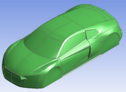
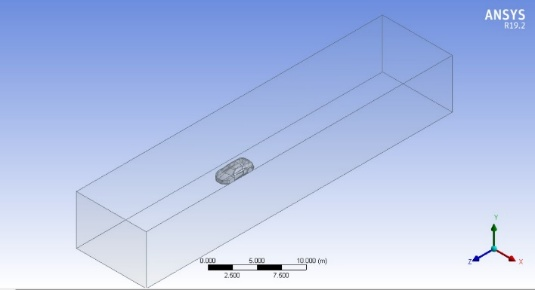
Computational domains are simplified representations of physical domains, including geometric forms and their boundary conditions. Although it captures all the essential physical characteristics of the problem, it ignores minor details. During CFD simulations, the computational domain refers to the space in which the solution is computed following the ERCOFTAC Association database. This is such as those referred to in [43]. A computational grid or mesh is required to solve the discretized equations of fluid flows. The solid model of the Audi car is shown in Figure 9; the geometry and domain of the prototype Audi R8 have been drawn by the design modeler in Figure 10.
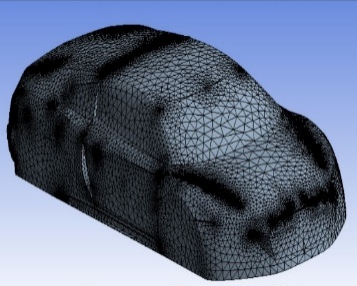
Within the ANSYS Workbench, the Meshing component was used to generate the computational mesh for the fluid domain. A tetrahedral cell configuration was adopted due to the intricate geometry of the car. As a result of the complexities of the car's curvatures, a refined mesh was applied specifically to its surface. A description of mesh size and quality is provided in Table 1 and a sample mesh is shown in Figure 11.
| Item |
|
|
||||
|---|---|---|---|---|---|---|
| No. of elements | 1,113,646 | 1,928,879 | ||||
| No. of nodes | 208,463 | 357,002 | ||||
| Minimum edge length | 0.018261 mm | 0.018261 mm | ||||
| Aspect ratio | 1.8916 | 1.8733 | ||||
| Average skewness | 0.23154 | 0.23151 | ||||
| Average element quality | 0.83454 | 0.83494 |
In this simulation, K-epsilon turbulence is used as the turbulence model. However, it may not be appropriate for situations involving large adverse pressure gradients. To accurately represent turbulent properties in the flow, two additional transport equations are included in this two-equation model. Consequently, historical effects such as convection and diffusion of turbulent energy can be accounted for in the model. As a measure of turbulent kinetic energy, the first transport variable is turbulent kinetic energy. The second variable is turbulent dissipation, which determines the scale at which the turbulence occurs. Additionally, the K-epsilon model has a good performance away from wall boundaries. An inlet plane, referred to as "Inlet," is characterized by an air velocity inlet of 72 km/h, which is equivalent to 20 m/s. Additionally, the turbulent intensity at the inlet is 5% and the turbulent viscosity ratio is 10. Additionally, the car's body is designed with stationary walls, with a "No Slip" shear condition and a "Standard" roughness model. The outlet is referred to as "Outlet" and is equipped with an "Absolute" backflow reference frame. It should also be noted that the convergence tolerance was set at .
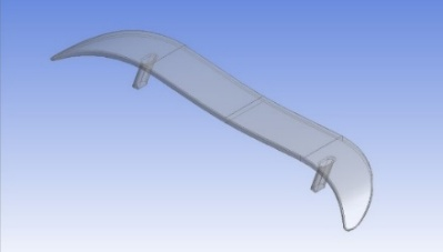
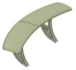
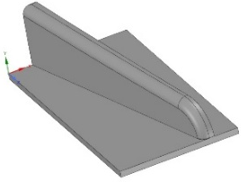
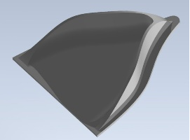
Various spoilers and VGs are being tested as part of the research. Figures 12 and 13 illustrate the proposed spoilers and VGs, respectively. A number of spoilers have been proposed, including pedestal spoilers, trunk spoilers, and wave spoilers, whereas VGs have been proposed, including Gothic, Airtap, and B2 spirit VGs.


Tables 2 and 3 present the results of the spoilers' and VGs' simulations.
|
|
|
|
|
||||||||||
|---|---|---|---|---|---|---|---|---|---|---|---|---|---|---|
| Without Spoiler | 82.60 | 0.225 | 87.52 | 0.238 | ||||||||||
| Pedestal | 76.06 | 0.207 | 67.71 | 0.184 | ||||||||||
| Trunk Spoiler | 76.88 | 0.209 | 32.59 | 0.088 | ||||||||||
| Wave | 78.46 | 0.213 | 40.93 | 0.111 |
By creating a downward force at the rear end of the car, a spoiler reduces the lift coefficient of the vehicle, thereby increasing the contact between the tires and the road. Depending on the shape, size, position, and angle of the spoiler, the impact of the spoiler on the car's lift and drag coefficients will vary. According to this study, adding a trunk spoiler can decrease the lift coefficient by up to 63%. As can be observed, this spoiler has a streamlined shape and curved edges, and it is also inclined, which helps reduce the force acting on it and reduce the drag coefficient by up to 7%. A spoiler can therefore enhance a vehicle's handling, performance, efficiency, and mileage at high speeds. By installing a pedestal spoiler, the lift coefficient is reduced by 22.7%, while the drag coefficient is reduced by 8%. The lift coefficient decreases by 53% in the wave spoiler case and the drag coefficient decreases by 5%. The trunk spoiler was found to be the most efficient option in these simulations, according to these simulations.
|
|
|
|
|
||||||||||
|---|---|---|---|---|---|---|---|---|---|---|---|---|---|---|
| Without VGs | 82.60 | 0.225 | 87.52 | 0.238 | ||||||||||
| Airtap | 80.12 | 0.218 | 82.64 | 0.224 | ||||||||||
| Gothic | 74.57 | 0.203 | 63.96 | 0.174 | ||||||||||
| B2 Spirit | 75.77 | 0.206 | 69.27 | 0.189 |
Different VGs can influence a car's coefficient of drag and lift coefficient in different ways, depending on their size, shape, and location. By creating a more streamline shape at the rear end of a vehicle, VGs reduce the coefficient of drag of that vehicle. Furthermore, VGs can alter the pressure distribution on a car's surface in order to influence the lift coefficient. Consequently, the effect of vortex generators on a car in terms of drag coefficient and lift coefficient depends on various factors. These factors include the geometry of the car, the flow conditions, and the design of the VG itself. The use of VGs can enhance the aerodynamic performance as well as the fuel efficiency and stability of automobiles. Due to the fact that Gothic VGs are rectangular blocks with fins on the surface, adding VGs can reduce the lift coefficient by 27%. In the boundary layer, the fin is angled to create vortices that mix the free stream air with the low density air, and thus decrease the drag coefficient by up to 9.8%. The B2 spirit reduces the lift coefficient by 20.6%, and the drag coefficient by 8.4%. By contrast, the lift coefficient decreases by 5.9% and the drag coefficient decreases by 3.1% in the Airtap VG case. These calculations indicate that Gothic VG performs best in simulations.
In light of the results in Table 3, Gothic VG was the best VG. As a result, the simulation was conducted on numbers 1, 3, and 5 VGs. A summary of the results can be found in Table 4, Figures 14 and 15.
|
|
|
|
|
||||||||||
|---|---|---|---|---|---|---|---|---|---|---|---|---|---|---|
| No VGs | 82.60 | 0.225 | 87.52 | 0.238 | ||||||||||
| 1 | 74.57 | 0.203 | 63.96 | 0.174 | ||||||||||
| 3 | 83.21 | 0.226 | 82.24 | 0.223 | ||||||||||
| 5 | 77.10 | 0.209 | 70.86 | 0.193 |

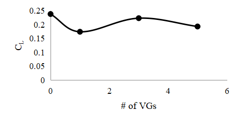
Table 4 shows that increasing the number of VGs on a car does not necessarily improve performance unless the placement and design of the VGs are optimized for the specific car and flow conditions. The use of VGs can improve the aerodynamics of a vehicle, but caution should be exercised when using them.
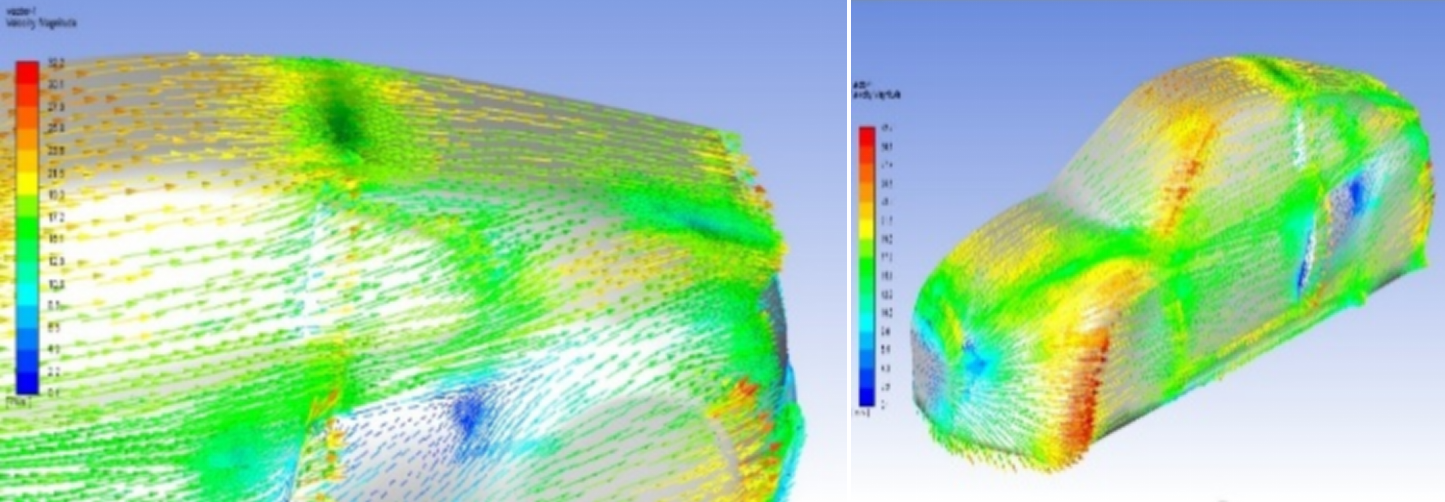
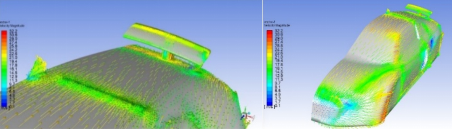
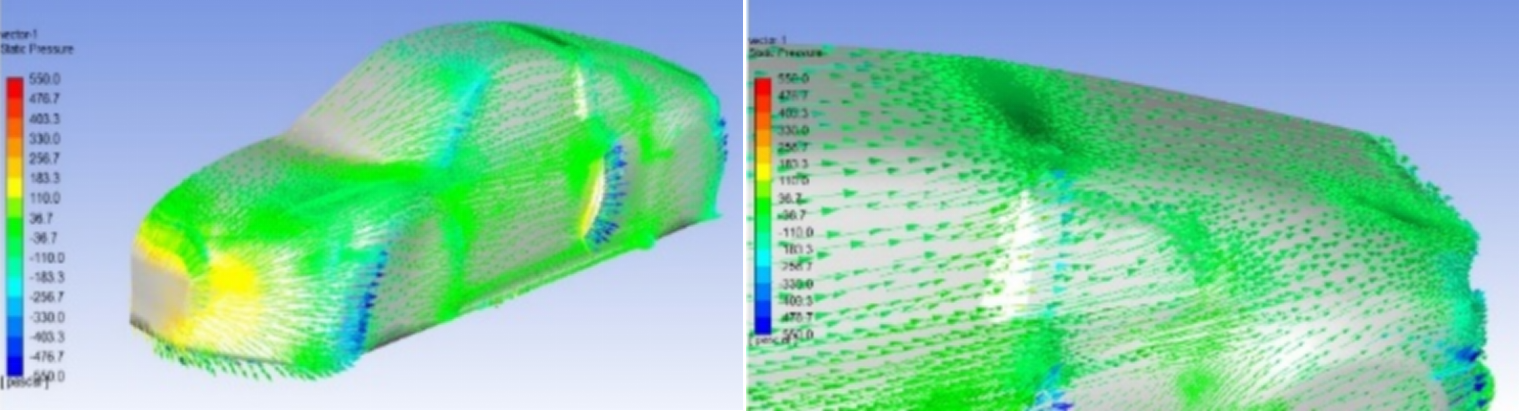
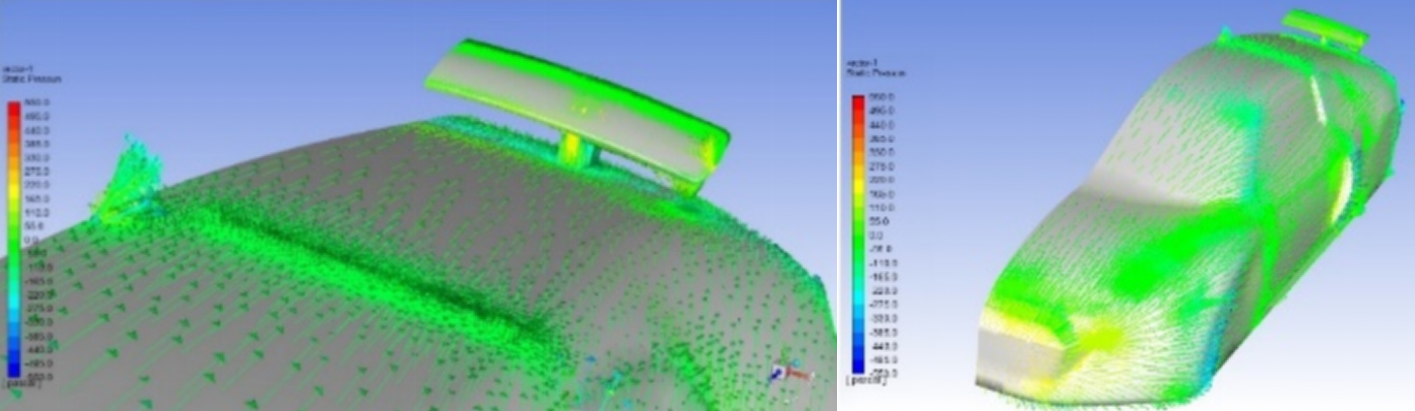
According to the data presented in Tables 1 and 2, the trunk spoiler emerged as the top-performing spoiler, while the Gothic Vertical Grip (VG) proved to be the most effective VG. Using the simulation, it was examined the combined impact of incorporating both the trunk spoiler and Gothic VG as shown in Table 5 and Figures 16, 17, 18 and 19.
|
|
|
|
||||||||
|---|---|---|---|---|---|---|---|---|---|---|---|
| 69.25 | 0.188 | 63.36 | 0.172 |
Based on Table 5, it is found that the lift coefficient has been reduced by 27.7%, while the drag coefficient has been reduced by 16.45%.
Energy generation and consumption are fundamentally influenced by aerodynamic principles. Aerodynamics plays a significant role in both the performance and efficiency of an automobile. This paper aims to provide a review of some of the literature available on spoilers and vortex generators (VGs). Then, it examines the effect of various types of air spoilers and VGs on an Audi R8 2014 vehicle using ANSYS Fluent 19.2. In order to conduct the simulation, the vehicle has been modified in order to accommodate computational fluid dynamics (CFD). A brief description of the simulation process has been provided. Different spoilers have been proposed, including pedestal spoilers, trunk spoilers, and wave spoilers. In addition, Gothic, Airtap, and B2 spirit VGs have been proposed. Based on the simulation results, the following conclusions were reached:
The trunk spoiler is the most effective among the proposed spoilers with 63% and 7% reductions in lift and drag coefficients respectively.
The pedestal spoiler resulted in a reduction of 22.7% in lift coefficient and an 8% reduction in drag coefficient.
In the case of a wave spoiler, the lift coefficient decreases by 53% and the drag coefficient decreases by 5%.
The Gothic VG is the best among VGs.
By adding Gothic VGs, the lift coefficient can be reduced by 27% due to their rectangular shape and fins on the surface. An angled fin creates vortices that mix free stream air with low density air in the boundary layer, thereby reducing drag by up to 9.8%.
In the B2 Spirit VG, the lift coefficient is reduced by 20.6% and the drag coefficient is reduced by 8.4%. In the Airtap VG case, the lift coefficient is reduced by 5.9% and the drag coefficient is reduced by 3.1%.
When the placement and design of VGs are optimized for the specific vehicle and flow conditions, increasing the number of VGs on a vehicle will not necessarily improve performance.
A vehicle's aerodynamics can be improved by using VGs, but caution should be exercised when they are used.
A combination of trunk spoiler and Gothic VGs has been tested, resulting in a 27.7% reduction in lift coefficient and a 16.45% reduction in drag coefficient.
In general, both spoilers and VGs can reduce the lift coefficient of the car, which improves the stability and handling at high speeds. Additionally, spoilers and VGs can reduce the drag coefficient of the car, improving fuel efficiency and performance. Moreover, spoilers and VGs are effective devices to enhance car aerodynamics, but they should be designed and applied carefully to achieve the most effective results. In essence, a spoiler diminishes the lift force and marginally decrease the drag coefficient. Concurrently, VGs play a pivotal role in minimizing drag force and slightly lowering the lift coefficient, with the potential to also induce an increase.
Additional checks are recommended to refine design parameters, such as the size, dimensions, position, direction of the spoiler, and the VG. Variables such as these are important for different car models and different flow conditions because they significantly influence lift and pull transactions. Additionally, to enhance aerodynamic analysis accuracy and efficiency, dynamic mesh simulation is recommended. This approach contributes to a greater understanding of aerodynamic performance by ensuring a more realistic representation of dynamic flow conditions. Measure context-related values in wind tunnel experiments to validate theoretical results. Finally, to validate and refine theoretical predictions, a comparative analysis of simulated and practical results will be conducted. This will increase the study's overall durability.
 Copyright © 2025 by the Author(s). Published by Institute of Emerging and Computer Engineers. This article is an open access article distributed under the terms and conditions of the Creative Commons Attribution (CC BY) license (https://creativecommons.org/licenses/by/4.0/), which permits use, sharing, adaptation, distribution and reproduction in any medium or format, as long as you give appropriate credit to the original author(s) and the source, provide a link to the Creative Commons licence, and indicate if changes were made.
 Sustainable Energy Control and Optimization
ISSN: request pending (Online) | ISSN: request pending (Print)
Email: [email protected]

Portico
All published articles are preserved here permanently:
https://www.portico.org/publishers/iece/