
Sustainable Energy Control and Optimization
ISSN: request pending (Online) | ISSN: request pending (Print)
Email: [email protected]

In the field of control systems, the Linear-Quadratic Regulator (LQR) and Linear-Quadratic Tracker (LQT) are two widely used methods for controlling linear dynamic systems [1]. These techniques focus on determining the optimal actions a control system must take to achieve specific objectives, primarily by minimizing system errors. The primary goal of these methods is to ensure that the system behaves in a desired manner while maintaining performance stability and reducing undesirable deviations.
LQR is designed to control a linear dynamic system by providing the appropriate input signals that guide the system towards a predefined goal [1]. For instance, in robotics, LQR can be used to ensure that a robot's position remains accurately controlled despite external disturbances. Similarly, in automotive applications, it can regulate a vehicle's speed or maintain stability during maneuvers. By minimizing a quadratic cost function, LQR efficiently balances control effort and state error, making it a preferred choice in many engineering applications [2, 3].
On the other hand, LQT extends LQR's capability by focusing on tracking a specific input signal. It is particularly useful for systems that need to follow a given trajectory or path, such as in navigation and control of autonomous vehicles, aircraft, or robotic systems. LQT aims to reduce the deviation between the system's output and the reference signal over time, ensuring precise tracking of the desired path or trajectory.
Both methods rely on solving linear differential equations that describe the dynamics of the system and use optimization techniques to determine the correct control actions [4, 5]. LQR and LQT have proven their effectiveness in various industrial and transportation applications, such as vehicle control, aircraft stability, and robotics, and continue to contribute to advancements in automation and intelligent systems. This research aims to explore these techniques in the context of DC motor control, analyzing their potential in optimizing performance and improving efficiency.
In the following section, previous research will be presented which still has similarities with the topic being discussed now. Here are some summaries of the research.
Research conducted by Firdaus (2024) compares two control methods that are often used in DC motor systems, namely Linear Quadratic Regulator (LQR) and Proportional-Integral-Derivative (PID) Controllers [1]. The main focus of this study is to improve the stability of the DC motor system, by highlighting the performance differences between the two methods.
LQR in this study: LQR is used to obtain optimal control with the aim of minimizing the cost function that includes position and speed errors and system input control. LQR works by calculating a feedback matrix that regulates the control input based on the state of the system, namely the position and speed of the motor. In the context of DC motors, LQR is able to provide more precise and stable settings, especially in systems that have disturbances or model uncertainty.
This study shows that LQR has advantages in terms of faster and more stable responses compared to PID in DC motor settings, especially when faced with variations or changes in load [1]. Compared to PID, LQR offers a more efficient solution in optimizing motor performance, given that PID tends to be more sensitive to parameter changes and tuning errors.
Overall, the results of this study show that the use of LQR in DC motor control provides better stability, with more structured programming to achieve optimal control under more complex conditions than PID.
In the study by Syaifudin (2024), the application of Linear Quadratic Regulator (LQR) and Linear Quadratic Tracking (LQT) control methods is explored for optimizing DC motor control systems [2]. The primary objective of this research is to improve energy efficiency for home industry players, leveraging the power of MATLAB Simulink for simulation.
LQR and MATLAB Simulation in the Study: In this research, MATLAB Simulink is utilized as the platform for simulating both LQR and LQT controllers. The simulation is key to assessing the performance and efficiency of the control methods applied to the DC motor system. MATLAB Simulink provides a comprehensive environment where the system model, including the DC motor dynamics, is represented with the relevant parameters for testing the control strategies [2].
The study demonstrates how the LQR controller is implemented in MATLAB Simulink, focusing on optimizing the system's energy usage while maintaining stability and performance. The simulation shows the advantages of LQR, particularly in minimizing the cost function related to energy consumption, motor speed, and position regulation. MATLAB's robust simulation environment allows for fine-tuning of the control parameters to achieve optimal performance and efficiency in a home industry setting.
In addition to LQR, the LQT method is also simulated in MATLAB Simulink to compare its effectiveness in achieving the desired control objectives. The results reveal that both LQR and LQT provide substantial improvements in energy efficiency and system performance, with LQR offering better stability and faster response times, especially in scenarios with varying load conditions.
Overall, the research highlights the importance of using MATLAB Simulink for simulating and optimizing DC motor control systems in real-world applications, particularly in enhancing energy efficiency for home industries [2, 3].
In the study by Satrianata (2024), the design and simulation of DC motor control systems using Linear Quadratic Regulator (LQR) and Linear Quadratic Tracking (LQT) are explored, with a goal of achieving an optimal control system [3]. The paper discusses the design principles of both controllers, along with their application in DC motor systems, aiming for improved performance and stability.
The study emphasizes the design process of both LQR and LQT controllers, specifically for DC motor control. The LQR design focuses on determining the optimal feedback gain matrix that minimizes a quadratic cost function, which is based on the error in the system (e.g., position and speed) and control efforts. In this study, the LQR design procedure involves setting up the state-space model of the DC motor, defining the weighting matrices, and then calculating the optimal feedback gain using MATLAB tools.
The LQT design, on the other hand, is extended to include tracking capabilities, where the goal is not only to stabilize the system but also to track a desired reference trajectory. The LQT controller requires a similar design process to LQR but incorporates additional terms in the cost function to account for tracking errors. This allows the system to follow a specific reference while still maintaining optimal control performance [3, 4].
The paper also describes how both controllers are simulated in MATLAB Simulink, where the system's state-space representation and control law are implemented. The simulation results demonstrate the effectiveness of the LQR in stabilizing the DC motor with minimal control effort, while the LQT shows better tracking performance for systems where reference following is critical.
The comparison between LQR and LQT in the simulation highlights the strengths of each method. The LQR controller provides robust stability and fast response times, making it ideal for scenarios where the system needs to be quickly stabilized [1, 3]. Meanwhile, LQT is shown to excel in scenarios where the system must follow a precise reference path, with the additional benefit of improving the tracking performance without sacrificing stability.
Overall, the study underscores the importance of designing LQR and LQT controllers to meet the specific needs of DC motor control systems, ensuring both optimal performance and efficiency in various operational conditions.
This section will discuss the methods used in this research. will be described in the research stages in the following subsections.
This research process follows several systematic stages designed to produce a deep understanding of the application of Linear Quadratic Regulator (LQR) and Linear Quadratic Tracking (LQT) on the control system of the BN12 DC Motor. The main steps in this study are as follows:
Literature Studies
The first stage in this study involves an extensive literature search to gather relevant references. The literature review serves as the foundation for understanding DC motor control principles, as well as the theoretical frameworks behind the LQR and LQT methods. This step includes analyzing scientific articles, peer-reviewed journals, datasheets, and textbooks that provide a comprehensive background on the operation and optimization of DC motors, control theory, and algorithm applications [5, 6]. A solid understanding of these sources helps in forming the theoretical base necessary for the subsequent stages of the study.Mathematical Model Creation
Once the theory underlying DC motor control has been understood, the next step is to create a mathematical model representing the dynamic system of the BN12 DC motor. This model will describe the physical parameters and operational behaviors of the motor, including its response to inputs, such as voltage and current, and how it interacts with external disturbances [7, 8]. The mathematical model serves as a tool for simulating the motor's behavior under different control algorithms. This model will also be used to validate the theoretical concepts obtained during the literature study and to ensure that the system's real-world behavior aligns with the expectations of the control methods.Network Creation
In this stage, the DC motor control system is developed using MATLAB Simulink software. The objective here is to design a simulation model that integrates both the DC motor and the control algorithms (LQR and LQT). This step involves creating the motor's control circuit and incorporating the LQR and LQT algorithms to regulate the motor's behavior. To ensure the robustness of the system, various testing scenarios are performed, including simulations with noise disturbances that could affect motor performance [9]. The goal is to assess how well the system maintains control and stability under varying conditions.Results and Discussion
Once the control system model is established, the simulation results are generated and analyzed to evaluate the performance of the motor under different control methods. The analysis focuses on comparing the performance of LQR and LQT in terms of motor efficiency, response time, and ability to handle external noise. A detailed discussion will highlight how each algorithm performs under different configurations and which method provides better control and stability for the DC motor.Drawing Conclusions
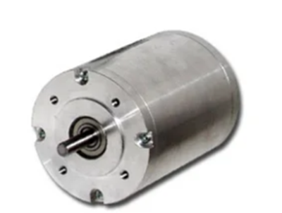
The final stage involves synthesizing the results from the simulation and analysis to draw meaningful conclusions about the effectiveness of using LQR and LQT for controlling DC motors. The conclusions will reflect on the relative advantages and limitations of each method in terms of optimization, robustness, and practical application. This step will also provide insights into how these control strategies can be further refined or applied in real-world DC motor systems. Ultimately, the research will contribute to a deeper understanding of how LQR and LQT can be effectively utilized for optimizing the performance of DC motors in various technological fields.The motor used in this study is the BN12 DC Motor, which is chosen for its well-documented specifications and suitability for control system experiments. The technical specifications of the BN12 DC Motor are crucial for the mathematical calculations and modeling performed throughout this research, as they define the parameters that govern the motor's dynamic behavior.
These specifications include key parameters such as the motor's voltage rating, current consumption, power output, torque characteristics, speed range, and mechanical dimensions, all of which play an important role in the system's modeling and control strategies [10, 11]. Additionally, the motor's moment of inertia, resistance, and inductance are necessary for accurately describing the motor's physical properties and ensuring that the control algorithms (LQR and LQT) are optimized for its specific characteristics. The BN12 DC motor is illustrated in Figure 1.
By integrating these specifications into the mathematical model, the study ensures that the simulation results accurately reflect the real-world behavior of the BN12 DC Motor, facilitating effective control strategy testing. The following image presents the motor's technical specifications, which will guide the model development and control system design [12]. Figure 2 presents the motorbike specifications.

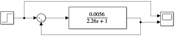
These specifications will guide the setup of the simulation environment in MATLAB Simulink, allowing for accurate testing and evaluation of the motor's performance under various control scenarios. DC motor 1st order function transfer equation:
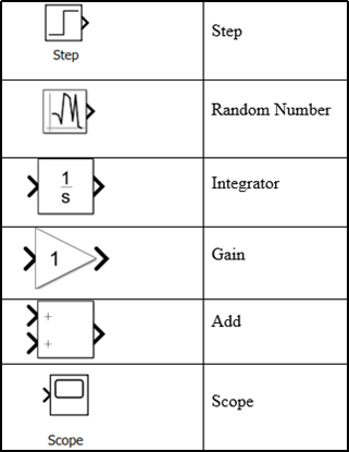
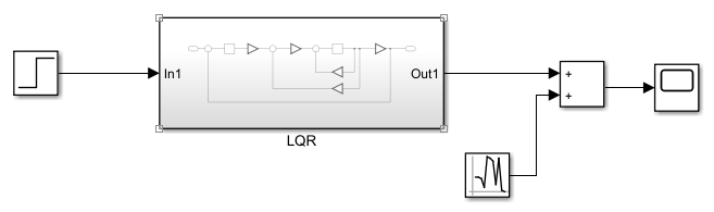
To build a system simulation model, various components are utilized within MATLAB Simulink software [13, 14]. Simulink provides a graphical environment where users can model, simulate, and analyze dynamic systems using pre-built blocks that represent physical components, mathematical operations, and control algorithms. The components used in this study are selected to accurately represent the behavior of the BN12 DC motor and integrate the LQR and LQT control strategies.
Simulink blocks include modules for defining the DC motor's electrical and mechanical characteristics, such as voltage input, current measurement, speed, and torque outputs [15, 16]. Additionally, blocks for the LQR and LQT controllers are incorporated to implement optimal control based on state feedback and tracking. These blocks interact seamlessly to simulate the motor's response to various inputs and disturbances, providing valuable insights into system behavior.
Moreover, essential blocks for signal processing, error tracking, and performance analysis are included to monitor and evaluate the system's behavior during simulations [17, 18]. By connecting these components in Simulink, the system's dynamics can be visualized in real time, enabling easy adjustments and optimizations to the control parameters [19].
A summary of the key components used in this study can be seen in Figure 3, which provides a list of Simulink blocks and their respective functions within the simulation model. These components are crucial for building a comprehensive system that accurately reflects the behavior of the DC motor under the influence of the control algorithms [20].
In this research, the BN12 DC motor control system is optimized using the Linear Quadratic Regulator (LQR) technique, aiming to achieve the best control performance by factoring in cost criteria that include the squared error and control energy. The DC motor's mathematical model incorporates several parameters, such as moment of inertia (J), damping coefficient (b), motor constant (K), resistance (R), and inductance (L). These parameters are fundamental for developing a state-space system, represented by matrices A, B, and C. To attain optimal performance, the LQR matrix is calculated by carefully selecting appropriate values for the Q and R matrices, which helps in balancing the system's response and the applied control inputs.
During the controller design, explicit constraints such as actuator limits or state bounds were not imposed directly within the control formulation. However, these practical considerations were indirectly addressed through careful selection of design parameters. For the LQR method, the weighting matrices Q and R were tuned to prioritize stability, fast response, and minimal overshoot, ensuring that the system behavior remains within acceptable operational ranges. Similarly, in the pole placement approach, the selected poles were chosen to ensure a well-damped and responsive closed-loop system that avoids aggressive control actions.
% OPTIMIZATION OF LQR SYSTEM ON DC MOTORS Clear; CLC; % DC Motor Models J = 28.2; b= 0.1; K= 0.144; R= 0.93; L = 0.000254; % J = Moment of Inertia, b = Attenuation Ratio, K= Constant, R= Resistance, L= Inductance A = [-b/J K/J; -K/L -R/L]; B = [0; 1/L]; C = [1 0]; AA = [A zeros(2,1); -C 0]; BB = [B; 0]; % Pole Placement J = [-3 -4 -5]; K = acker(AA,BB,J); KI = -K(3); KK = [K(1) K(2)]; % LQR Matrix Q = [1 0 0; 0 1 0; 0 0 1000]; R = [1]; K_lqr = lqr(AA,BB,Q,R); KI2 = -K_lqr(3); KK2 = [K_lqr(1) K_lqr(2)];
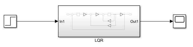
The following is a display of Figures 4, 5, 6, and 7 which show the simulation circuit used.

Furthermore, the Linear Quadratic Tracking (LQT) method is employed to enhance the performance of the DC motor control system by focusing on more precise trajectory tracking. In the LQT approach, the optimization process includes determining smaller values for the Q and R matrices to ensure optimal performance during the tracking process. The calculation of the S matrix, derived from the Riccati equation, plays a crucial role in determining the desired feedback gain. This feedback gain enables more adaptive control of the motor, improving its response and accuracy in following the desired trajectory.
% LQT SYSTEM OPTIMIZATION ON DC MOTORS Clear; CLC; % DC Motor Models J = 49.430; b= 0.1; K= 0.022; R= 0.10; L = 0.000012; % J = Moment of Inertia, b = Attenuation Ratio, K= Constant, R= Resistance, L= Inductance A = [-b/J K/J; -K/L -R/L]; B = [0; 1/L]; C = [1 0]; Q=10; R=0.0000000001; W=C'*Q; [S,o,m,n] = care(A,B,C'*Q*C,R); K = inv(R)*B'*S; ACL = (A-B*K)'; L = inv(R)*B';
In this section, it will be divided into 2 types of experimental results. Normal experimental results and experimental results with noise. The parameters of the proposed controller were selected based on system characteristics and desired performance objectives. For the pole placement method, poles were assigned at , , and to ensure sufficient damping and a fast transient response. In the LQR design, the Q and R matrices were tuned experimentally to balance between state error minimization and control effort. These choices were guided by simulationbased trialanderror optimization, The following is the explanation.
Simulation LQR without noise
The noiseless LQR simulation demonstrates a highly stable step response for the BN12 DC motor, with the output amplitude settling at approximately 1. This indicates that the system has successfully achieved its desired state, maintaining steady performance without significant deviations. The system's rise time was recorded at 1.109 seconds, which is a relatively fast response time, signifying the effectiveness of the LQR control in quickly driving the motor to its target state.Additionally, the simulation results revealed an exceptionally small overshoot and undershoot of only 0.505%, indicating that the motor was able to reach the desired setpoint without significant fluctuations or oscillations. This minimal deviation showcases the controller's ability to maintain a smooth and precise response, ensuring that the motor operates efficiently without excessive energy consumption or instability. The performance metrics obtained from the noiseless LQR simulation underscore the method's potential in providing highly accurate and stable control for the BN12 DC motor, making it an effective solution for real-world applications where precision and stability are critical. Figure 8 shows the noise-free step response.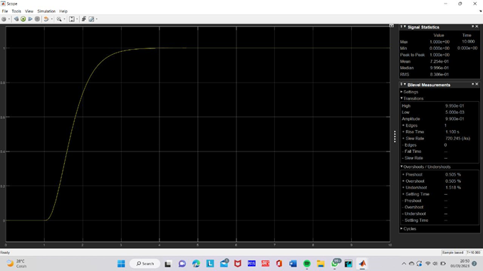
Simulation LQR with noise
In the LQR simulation with noise, the BN12 DC motor system exhibits noticeable fluctuations, primarily due to the influence of external disturbances or noise within the system. These disturbances result in an increased level of instability, which is reflected in the simulation results shown in Figure 9. The amplitude of the system's response is significantly lower, reaching only 0.67, compared to the noiseless case, suggesting that the motor's ability to reach and maintain the target value is impaired by the presence of noise.Furthermore, the rise time was recorded at 52.720 ms, indicating that the system still responds relatively quickly, but not as efficiently as in the noiseless scenario. However, the most striking observation is the extremely large overshoot of 102.942%, which shows that the system drastically exceeds the target value before settling. This is followed by a considerable undershoot of -87.686%, highlighting a significant delay and fluctuation before the motor stabilizes.These results underscore the negative impact of noise on the system's performance. The large overshoot and undershoot demonstrate that noise disrupts the controller's ability to stabilize the system and maintain precise control. This simulation highlights the challenges associated with noise interference in control systems and emphasizes the need for robust control strategies that can minimize the adverse effects of disturbances, ensuring stable and accurate motor performance under real-world conditions.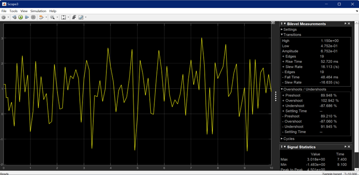
In this section, it will be divided into 2 types of experimental results. Normal experimental results and experimental results with noise. The following is the explanation.
Simulation LQR without noise
Systems utilizing LQT (Linear Quadratic Tracking) exhibit distinctly different results compared to LQR (Linear Quadratic Regulator). In the LQT simulation, while the amplitude of the system response reached 9.925, which is a higher value than in the LQR case, the system exhibited a high overshoot of 5.58%. This overshoot suggests that there may be a deficiency or defect in the control system that needs to be addressed. The presence of such a notable overshoot implies that the system initially exceeds the desired target before stabilizing, which can potentially lead to instability in practical applications.Despite the higher overshoot, the LQT-controlled system demonstrates a more responsive behavior compared to LQR. The tracking ability of LQT allows for faster adaptation to changes in input signals, making it more effective in scenarios where the system needs to follow a dynamically changing reference. This responsiveness, however, comes at the cost of reduced accuracy, as seen in the overshoot and slightly unstable settling.The trade-off between response speed and stability is evident here: while LQT excels in tracking speed and adaptability, it introduces a risk of over-correction, leading to higher overshoots. These issues need to be addressed through further tuning of the control parameters or the implementation of additional techniques, such as filtering or more refined feedback loops, to minimize overshoot and improve the system's overall accuracy without sacrificing its responsiveness.Thus, while LQT offers better performance in terms of quick adaptation to changes, it is crucial to find a balance between responsiveness and control stability to ensure that the system remains both efficient and accurate in real-world applications. Figure 10 shows the step response of the noise-free LQT.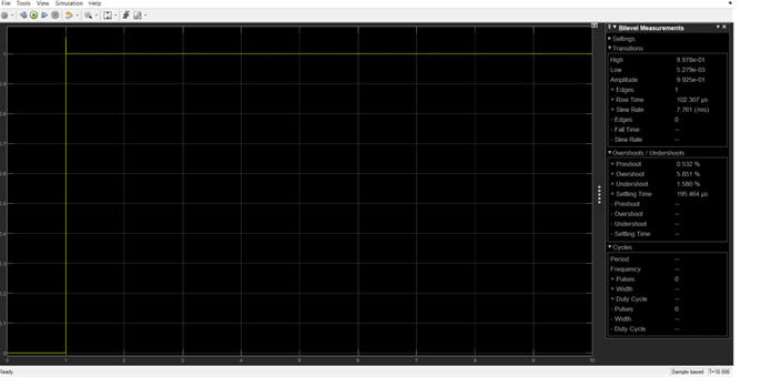
Simulation LQR with noise
Under noisy conditions, the LQT system exhibited considerable fluctuations in the output graph, as shown in Figure 11, which are indicative of the system's challenges in handling external disturbances or noise. The undershoot of -9.136% and the overshoot of 13.219% highlight a significant instability in the system's performance. The motor was unable to settle around the desired setpoint, and instead, it exhibited oscillations that resulted in substantial deviations both above and below the target value. These deviations are a clear indication of the system's struggle to maintain accurate tracking in the presence of noise, revealing a critical issue with the system's robustness.Despite the relatively fast rise time of 50.013 ms, which suggests that the system initially responds quickly to changes, the LQT control algorithm was unable to successfully maintain the trajectory or target setpoint due to the interference caused by the noise. This highlights a fundamental weakness in the LQT approach when exposed to disturbances. The system's response time is fast, but the inability to accurately track the desired reference signal results in poor overall performance, as seen in the high overshoot and undershoot.The results underscore the LQT system's vulnerability to noise, particularly in scenarios where high precision is required. Although LQT is effective in situations that demand fast response and adaptability, it is less robust in environments with significant noise or disturbances. This suggests the need for further refinement in the control strategy, such as incorporating noise-filtering techniques or hybrid control methods, to enhance the LQT system's ability to effectively cope with interference while maintaining both responsiveness and stability.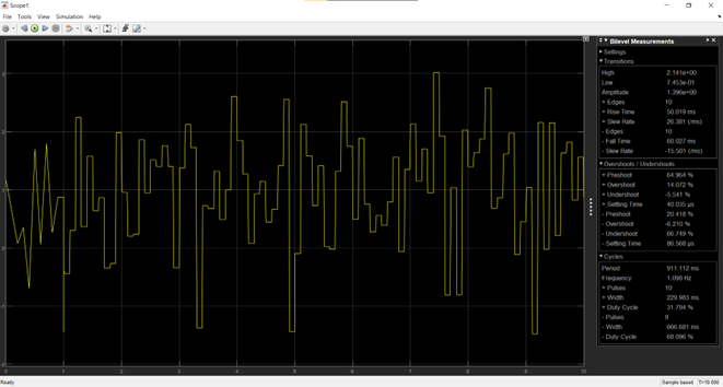
Based on the simulation results, the BN12 DC motor control system using the LQR method outperforms LQT, particularly in stability and quick setpoint achievement. LQR ensures fast response with minimal overshoot (0.505%) and undershoot, maintaining precise control with minimal deviation. In contrast, LQT achieves a higher amplitude but suffers from significant overshoot (5.58%) and fluctuations, especially in noisy conditions, leading to instability and less accurate tracking.
Regarding robustness, LQR shows strong performance in noiseless conditions but struggles under noise, with significant overshoot (102.942%) and undershoot (-87.686%), highlighting its vulnerability to disturbances. LQT, while responsive, faces greater instability under noise, with overshoot and undershoot reaching 13.219% and -9.136%, respectively, revealing its lower robustness.
Therefore, LQR is more suitable for applications where stability and precision are critical in noiseless environments, while its performance degrades significantly under noisy conditions. Although LQT offers faster adaptation, it is less effective in noisy or disturbed environments and requires further refinement.
Despite these promising results, the study's simulations omit real-world factors like sensor noise, actuator delays, and varying load conditions. Future work should address these limitations to validate the control strategies' real-time performance and robustness.
 Copyright © 2025 by the Author(s). Published by Institute of Emerging and Computer Engineers. This article is an open access article distributed under the terms and conditions of the Creative Commons Attribution (CC BY) license (https://creativecommons.org/licenses/by/4.0/), which permits use, sharing, adaptation, distribution and reproduction in any medium or format, as long as you give appropriate credit to the original author(s) and the source, provide a link to the Creative Commons licence, and indicate if changes were made.
 Sustainable Energy Control and Optimization
ISSN: request pending (Online) | ISSN: request pending (Print)
Email: [email protected]

Portico
All published articles are preserved here permanently:
https://www.portico.org/publishers/iece/